Monday, August 10, 2015

Cheap and Cheerful Octal BIAS Probes

How to make a set of BIAS probes

In the process of making some new BIAS probes for testing idle currents in valve amps I decided to hastily document the process for anyone else out there wishing to build something similar. I've seen plenty of different types of probes out there, from the downright dangerous to the ludicrously expensive.

I took a handful of parts plus some 5 minute epoxy, plenty of patience and some tricky soldering to make 4 new probes to replace my previous aging ones, one of which had a broken keyway.

This project shall be documented mainly in pictures with a minimum of text due to the usual time restraints.

Parts:
RS part number 402-715 Octal Relay Socket
Multicomp TEST-7CN Test Pin

Vishay Dale RS02B1R000FE70 Wirewound 1Ohm Resistor
Antique Electronics part number P-SP8-476 Octal Base

20AWG tinned copper wire
5 minute epoxy
3mm heatshrink


Main parts


Take the Octal Relay Socket and drill out the bottom, widening the hole as much as possible. I used a step bit in a hand drill for this job. Doesn't matter if it's messy, it will be hidden away once completed. File out with a half round file if you need to clean it up a bit.

Bottom of Socket drilled out

Drill a 2.5mm hole in the side of the Socket body, make sure that when the top is done up tight it will align roughly with Pin 8. I also drilled out the slot next to the brass insert to 2.5mm, these 2 holes will take the Test Pin ceramic bases.

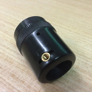
Holes drilled for Test Pins

Prepare some 20AWG or similar tinned copper wire (hint for straightening, cut a length, put one end in vise, one end in bull nose pliers and 'snap'it taut a couple of times, it will straighten nicely). Notice that the lengths I have cut get progressively shorter, this is to aid in the insertion process, one at a time goes much more easily into the Octal Base than all wires at once.

Wires and resistor prepared
Solder wires around the socket, making sure that the resistor is on Pin 8 and the wires step progressively from shortest to longest.
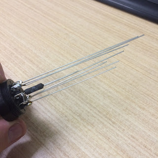
Soldered

Had to extend the resistor lead slightly, added heat shrink to everything, be sure that heat shrink is not too long or the socket and base will have difficulty fitting together. Ensure that resistor lead has space for solder joint either side of the resistor body. In the photo below you can see that I have trimmed the resistor lead and shaped it to meet up with the top 2.5mm hole previously drilled in the Socket body.

Heat Shrinked!

I have filled up the keyway in the Octal Base with epoxy, this should stop it from breaking quite so easily. something keyways are prone to if they are in and out of amps all the time.

Epoxy being injected
 
Epoxy drying
Now to put all the parts together, add some epoxy into the threads of the Octal Relay Base and then screw together, making absolutely sure that the resistor lines up with the 2x 2.5mm holes drilled in the Socket body.

More Epoxy

Now, this is the trickiest part and also the part I have neglected to photograph for your convenience! (Apologies, but you should be able to work it out). Once the Base is glued and screwed onto the Relay Socket Body it is time to gently push some of the wires out of the way, insert a Test Pin nto the hole nearest the 'top' of the socket and very carefully use a slender soldering iron to get some solder flowing between the Test Pin and the protruding little bit of remnant lead from the resistor. This can be very frustrating and could be refined further as a process, I leave that up to you. Once the upper Test Pin is in place you can position the lower Test Pin which should be much easier owing to its position. Solder this to the other side of the resistor to give you your test clip points. Gently reshape the remaining wires and prepare to insert the whole lot into the Octal Base. Previously I have 'potted' the whole assembly with silicon but I have decided not to do that this time, it may have been overkill.

Epoxy the two parts together ensuring that all wires go into their respective holes and that the resistor is on PIN 8. Let the epoxy cure, trim the leads and solder up the pins. Test for continuity and of course your 1Ohm at PIN 8. You might also want to dab a little epoxy around the bases of the Test Pins so they do not move.

Almost there

 And there we have it, a batch of my ugly but functional BIAS probes.

Finished product, a bit messy but they work well
 

Monday, July 8, 2013

Valvolux Repair Services Suspended Indefinitely


As of August 2013 Valvolux Amplifiers will no longer be offering repair services.
 
This has been a particularly difficult decision to make but I feel it is time to take a break for the foreseeable future, concentrate on product development and hopefully find the time to play some actual music of my own.

 
Valvolux Amplifiers will continue to function as a supplier of parts and accessories, maybe at some point in future I can start up the repairs again if conditions call for it.

 
In the meantime to all my valued clients I have assisted over the past 7 years I say a big thank you for your support and can can only offer my sincere apologies at the notion that I am 'letting you all down'. I've met hundreds of great people through this business and I have appreciated every one of you and felt privileged to look after your amps.

 
All the best, Gavin V

Saturday, January 12, 2013

Building Valvolux's home - Part 2

Part two


Next up came installing a new window frame in order to replace the awful louvre window that was present. I had the window measured up and took delivery of the replacement in Western Red Cedar with 10mm panes. The old louvre window that was in there was levered out. When we unscrewed one of the metal louvre frames out popped this spider almost as big as my hand. It must have lived almost its whole life in there, there was no way it could have gotten out without us removing the panel. Scared the bejesus out of us!

The frame it is sitting on is approx 100mm wide
Old window frame is gone
New frame and panes installed
Starting to frame

Stud dividing wall goes up
Rear of the dividing stud wall before final sheeting


The framing was going up at the same time. I decided to divide the shed into tw parts, about one third of the way along in order to leave me a space for gardening tools, bikes and assorted junk so I constructed a stud wall across the width of the room.

Whilst it may appear that all this stuff is happening pretty quickly, don't be fooled, it is a trick of the interwebs. It took months and months of hard slog to get this all happening and writing this up for the blog makes me realise I could have taken a lot more photos in order to avoid apparent gaps in continuity.

It's also pretty lame that I am finishing off these blog posts about three years after completing the build! 
 

Repair Job #318 Steelphon GA810


I had this very unusual Italian Steelphon GA810 come in for repair and couldn’t seem to find too much info online about it, particularly in English. So I thought I better write up a blog post on it with some photos and take some voltage readings etc that might be of use to somebody out there.


When it came in the amp was humming dreadfully when powered on. This later turned out to be a faulty Electrolytic can capacitor. These types of can caps that have a single plastic thread at the bottom for mounting are not readily available so I had to widen the existing mounting hole and install a clamp style can capacitor in its place.


The output stage of this amp is a pair of 2N3055’s with rails at +40VDC and -40VDC. This particular example seems to be missing one of the output transistor PCB's as can be seen in the photos.


The preamp is driven by an ECL86 and 2 12AX7’s.

12AX7 plates measured at 182V, 139V, 100V and 101V.
ECL86 triode plate measured at 80V and pentode plate measured at 149V.


Overall, this amplifier sounds very nice, jangly and sparkling with tons of reverb on call. There is even an internal reverb depth control so you can set your max reverb where you like it. The tone turns to a nice crunch at higher volume.


The reverb pan is a delicate arrangement!


Rectification and filter stage
Preamp PCB underside

Preamp PCB top view
2N5322

2N5320
Power stage PCB top view
Output PCB
Seems to be missing an output PCB
This hardware keeps the two cabinet halves clamped
Faulty Faccon cap
New F&T 50+50uF cap installed


With thanks to Richard Walsh.

Wednesday, August 22, 2012

Building Valvolux's home - Part 1


Part one

Valvolux Amplifiers needed a permanent home, so high on the list of requirements when choosing an abode back in 2008 was a suitable garage or similar enclosed area that could be converted into a reasonably secure and insulated workspace for me to tinker in. It was important to provide a space that Valvolux could grow into without getting too cramped in the forseeable future.

So it was a stroke of fortune that my wife and I both fell in love with the house that is now our home, which just happened to have a large 2 car brick garage out the back. Much to my wife's delight I was determined to make this shed the most awesome room in the whole house.

With the rest of the house crumbling around us and biting off way more than we could chew we threw ourselves into some serious renovation work. (It is a testament to this that we spent the first year of our residency here sleeping in the loungeroom).

Brick, concrete and tin shell full of our 'stuff'

The shed was just a brick, concrete and tin shell of approximately 10 x 3.6 metres in dimension. A very large dog had been living in it and it really didn't smell too good. My plan was to turn it into a secure, well insulated and comfortable room in which I'd be happy to spend long hours working on electronics but also with a small area down one end for entertaining guests and receiving customers (and maybe we can fit a small bar in too – ed). I had a really good idea of what I wanted in my head so drawn up plans weren't necessary, I just decided to go for it and solve each problem as it arose.

The first job to tackle was replacing the rusting corrugated iron roof with zinc aluminium. I wanted to ensure absolutely no leaks in this building and to also negate any possibility of having to replace the roof later on down the track.
With the parts ordered and delivered we of course had to choose an insanely hot weekend in the middle of summer to work on a hot tin roof.


With the help of some mates we set about pulling the old sheets off, giving the woodwork a really good clean(including discovering the previous owner's little stash of naughty pictures cut neatly out of magazines and then crumpled up and stuffed into the eaves...strange indeed).

 Cleaning out the stickmag stash!

Great view from up here, looking forward to getting the shed roof vegetable garden happening one day. The Dandenongs are there somewhere in that low cloud


With the new roofing sheets already cut to size it was a fairly simple but physical task to put them in one by one and then secure the whole lot with hundreds of tek screws. 

Last one almost in. With thanks to Chris, Marco and Nanne

And so now with a new roof on it was time to start thinking interiors, this will be covered more fully in part two to be published soon.